


- Site Navigation -
Parallel Idler Roller Uses in Conveyor Return Systems: Specifications and Selection Guide
Author:yuexing Date:2026-06-12 20:18:17 Hits:83
The parallel idler roller is the workhorse of conveyor return systems across mining, cement, power generation, and bulk terminal operations. While much engineering attention focuses on the troughing idlers supporting the loaded belt, the return run—where the empty belt travels back to the tail pulley—relies on properly specified parallel idlers to maintain belt alignment, control sag, and provide a stable platform for optional cleaning components such as belt scrapers and spiral or comb idlers. For plant engineers and procurement professionals, understanding the uses, specifications, and selection criteria of parallel idler rollers is fundamental to designing reliable, low-maintenance conveyor systems.
What Is a Parallel Idler Roller and How Does It Function?
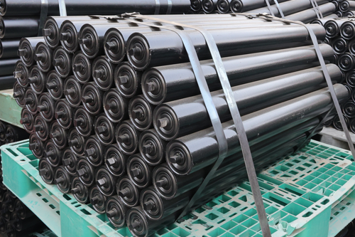
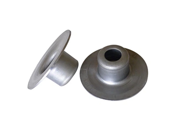
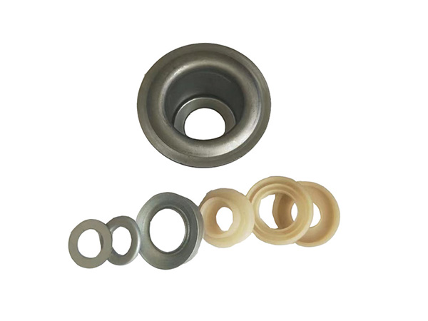
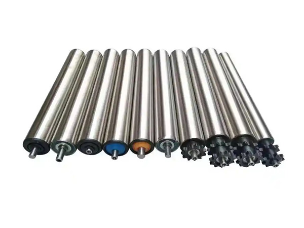
A parallel idler roller is a cylindrical conveyor roller mounted transversely across the conveyor frame to support the return (non-loaded) belt run. Unlike troughing idlers that cradle the belt in a troughed configuration, parallel idlers present a flat, horizontal support surface. Each parallel idler roller rotates freely on its shaft, supported by sealed bearings housed in end caps press-fitted to the roller shell.
The primary function of the parallel idler roller in return systems is to support the belt's dead weight and any residual carryback material, maintaining proper belt sag between support points and preventing the belt from contacting the conveyor gallery floor or structural members. Secondary functions include providing a stable mounting platform for belt cleaning devices and maintaining consistent belt tracking geometry on the return run.
Key Uses of Parallel Idler Rollers in Conveyor Return Systems
The parallel idler roller serves several critical functions in industrial conveyor return systems. The following applications represent the most common and technically significant uses:
Use 1: Return Belt Support and Sag Control
The fundamental use of a parallel idler roller is to support the return belt at regular intervals, controlling belt sag within acceptable limits. Excessive sag causes several problems: increased belt tension variation, reduced drive pulley friction angle, and potential belt contact with the conveyor stringer or walkway. Industry standards (CEMA, DIN 22101) recommend a maximum return belt sag of 1–2% of the idler spacing distance.
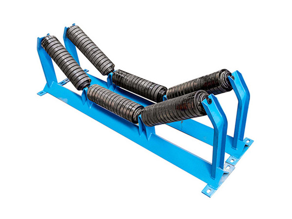
Use 2: Mounting Platform for Belt Cleaning Systems
Many belt cleaning systems—including belt scrapers, spiral idlers, and comb idlers—require a stable, flat support surface on the return run. The parallel idler roller provides this platform. In systems where comb idlers or spiral idlers are installed, they are typically mounted in the same frame positions as the standard parallel idlers they replace, ensuring structural compatibility and simplified retrofitting.
Use 3: Belt Tracking and Alignment Reference
The flat, horizontal orientation of the parallel idler roller provides a consistent geometric reference for belt tracking on the return run. While the idler itself does not actively correct misalignment (that function belongs to training idlers), the parallel idler's uniform support ensures that misalignment forces are consistent and detectable by downstream tracking sensors or training idler assemblies.
Use 4: Carryback Discharge Collection Point
In conveyor systems equipped with belt scrapers at the head pulley, the first parallel idler roller on the return run (located immediately downstream of the scraper) serves as the discharge collection point for scraper-removed carryback. Material dislodged by the scraper falls directly onto the gallery floor or into a collection chute positioned beneath this first parallel idler station.
Use 5: Vibration Damping and Belt Stability
Properly spaced parallel idler roller stations dampen belt vibration and resonance on long horizontal or inclined return runs. This is particularly important for high-speed conveyors (belt speeds above 3.5 m/s), where aerodynamic effects and belt stiffness variations can induce standing wave patterns that compromise tracking and increase spillage risk.
Specifications and Load Calculations for Parallel Idler Selection
Selecting the correct parallel idler roller for a conveyor return system requires calculating the maximum radial load each idler must support. The load calculation follows this general approach:
Return belt load per idler (kg) = (belt mass per meter × idler spacing) + (carryback mass per meter × idler spacing)
Where carryback mass is typically estimated at 0.5–2.0% of the loaded belt's material mass flow rate, depending on material characteristics and cleaning system effectiveness.
Based on this calculated load, the parallel idler roller is selected according to its rated bearing load capacity. CEMA provides standardized load rating tables for idler rollers based on belt width, idler diameter, and bearing series. Common parallel idler diameters for return systems range from 89 mm to 219 mm, with 133 mm and 159 mm being the most frequently specified sizes for medium-duty industrial conveyors.
Idler Spacing Rules for Return Systems
The spacing of parallel idler roller stations on the return run is governed by belt sag limits, belt tension, and material carryback characteristics. General spacing guidelines from CEMA and DIN standards are as follows:
Standard spacing: 2.5–3.5 m for belts ≤1,200 mm width with normal tension and minimal carryback.
Closer spacing (1.5–2.5 m): Recommended for belts >1,200 mm width, high carryback applications, or where comb/ spiral idlers are installed on the return run.
Maximum spacing: Never exceed 4.0 m for any return run application; excessive spacing causes belt flutter, tracking instability, and accelerated idler bearing wear due to shock loading.
When a parallel idler roller is replaced by a cleaning idler (spiral or comb type), the spacing should typically be reduced by 20–30% to maintain equivalent belt support and cleaning effectiveness.
Material and Construction Options for Parallel Idler Rollers
Parallel idler roller units are available in several construction variants to match application requirements:
Steel shell, painted: Most common and economical; suitable for dry, non-corrosive environments.
Steel shell, galvanized: Enhanced corrosion resistance for outdoor or high-humidity installations.
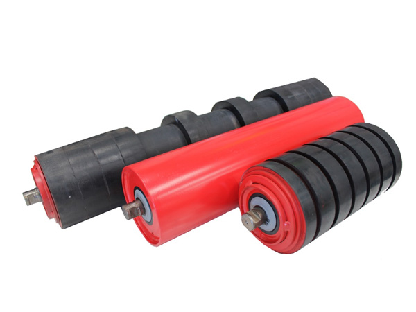
Rubber-disc parallel idler: Rubber discs mounted on a steel shaft; reduces belt cover wear and operates more quietly than steel shells. Preferred for food-grade or noise-sensitive applications.
HDPE (plastic) shell: Corrosion-proof and lightweight; suitable for chemical processing and coastal/marine conveyor environments.
Rubber-coated steel shell: Combines steel structural strength with rubber's low-surface-energy properties; used in sticky-material applications where carryback adhesion to the idler shell is a concern.
Maintenance Practices for Parallel Idler Roller Systems
The parallel idler roller is designed for low-maintenance operation, but systematic inspection remains essential for reliable performance. Recommended maintenance practices include:
Bearing lubrication: For grease-lubricated bearings, re-grease every 2,000–4,000 operating hours depending on environmental dust and moisture levels. Sealed-for-life bearing cartridges eliminate this requirement.
Shell condition inspection: Check for shell wear, corrosion, or deformation every 3,000 operating hours. Replace the idler roller when shell wall thickness at the contact surface falls below 70% of original specification.
Bearing play assessment: Measure radial and axial bearing play annually. Replace the idler when radial play exceeds 0.5 mm or axial play exceeds 1.0 mm.
Idler alignment verification: Verify that idler shafts remain perpendicular to the belt centerline during annual conveyor alignment checks. Misaligned parallel idlers accelerate belt edge wear and can induce tracking drift.
FAQ: Parallel Idler Roller Uses in Conveyor Return Systems
Q1: Can a parallel idler roller be used as a tracking idler?
A standard parallel idler roller is not a tracking idler and does not correct belt misalignment. However, it provides the stable support platform necessary for training idlers to function effectively. In some return run configurations, a single parallel idler station may be replaced by a training idler assembly to provide active tracking correction.
Q2: What is the typical service life of a parallel idler roller?
Service life depends on bearing type, environmental conditions, and load magnitude. Standard parallel idler roller units with sealed bearings in non-abrasive, indoor environments typically deliver 30,000–50,000 operating hours. Harsh outdoor or high-dust environments may reduce service life to 15,000–25,000 operating hours.
Q3: Are rubber-disc return idlers a type of parallel idler roller?
Yes, rubber-disc idlers are a variant of the parallel idler roller family. Instead of a continuous cylindrical shell, rubber discs are mounted at regular intervals along a central shaft. This design reduces belt contact area, lowers noise, and minimizes material buildup on the idler surface. Rubber-disc idlers are commonly used in food processing and light-industrial applications.
Q4: How does belt speed affect parallel idler roller selection?
Higher belt speeds increase the dynamic load on parallel idler roller bearings due to belt aerodynamic lift and increased rotational acceleration at each idler contact point. For belt speeds above 4.0 m/s, specify idler rollers with heavier-duty bearing series and verify that the idler shell's dynamic balance meets ISO 1536 Class Q or equivalent standards.
Q5: Can parallel idler rollers be retrofitted with spiral or comb idlers?
Yes, one of the primary uses of the parallel idler roller position is as a retrofit mounting point. Spiral or comb idlers are typically designed to mount in standard CEMA or DIN idler frames, allowing direct replacement of parallel idlers without structural modification to the conveyor stringer.
Conclusion
The parallel idler roller is a foundational component of conveyor return systems, providing essential belt support, sag control, and mounting infrastructure for cleaning and tracking devices. Its uses extend beyond simple load-bearing: it shapes belt dynamics on the return run, influences tracking stability, and determines the effectiveness of downstream cleaning systems.
For procurement and engineering teams specifying conveyor systems, correct selection of parallel idler roller diameter, bearing capacity, spacing, and shell material is a direct investment in conveyor reliability and operating cost control. When upgrading existing conveyors for improved carryback control, the parallel idler station is the standard retrofit location for installing spiral or comb idlers—making it a strategically important component in any comprehensive belt cleaning strategy.
References
Conveyor Equipment Manufacturers Association (CEMA). Belt Conveyors for Bulk Materials. 7th ed. Naples, FL: CEMA, 2014.
DIN 22101:2011. Continuous Conveyors – Belt Conveyors for Loose Bulk Materials – Basis for Calculation and Dimensioning. Berlin: DIN Deutsches Institut für Normung e.V., 2011.
Roberts, A.W. "The Influence of Idler Geometry and Spacing on Conveyor Belt Sag and Power Consumption." Bulk Solids Handling, vol. 18, no. 4, 1998, pp. 421–434.
ISO 1536:1999. Conveyor Belts – Specification for Rubber- and Plastics-Covered Conveyor Belting of Textile Construction. Geneva: International Organization for Standardization, 1999.
Goodyear Tire & Rubber Company. Conveyor Belt Design Manual. Akron, OH: Goodyear, 2005.

Contact Us
Tel:8615031765579
WhatsApp:+8615031765579
E-mail:905675277@qq.com
Add:Likou Village, Chenzhuang Town, Xian County, Hebei Province, China
Url:https://www.yxidlerrollers.com