


- Site Navigation -
Friction Idlers Applications in Conveyor Belt Systems: Working Principles and Selection Guide
Author:yuexing Date:2026-06-26 11:43:53 Hits:144
In inclined and declined conveyor systems, controlling belt motion during normal operation and emergency stop events is a critical safety and performance requirement. While brake systems at drive stations handle primary stopping functions, friction idlers provide a distributed, supplementary braking and speed-control mechanism along the conveyor length. These specialized idler rollers incorporate controlled friction elements that resist belt motion, preventing belt runaway on steep declines and stabilizing belt tension on inclined sections. For plant engineers, safety officers, and procurement professionals specifying conveyor systems in mining, cement, and bulk terminal operations, understanding the applications, working principles, and selection criteria of friction idlers is essential for designing safe, code-compliant material handling systems.
What Are Friction Idlers and How Do They Work?
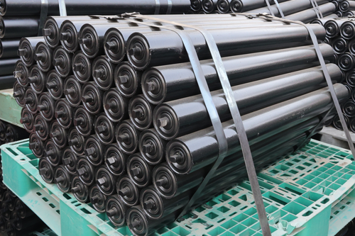
Friction idlers are conveyor idler rollers designed to introduce a controlled frictional resistance between the idler and the belt, creating a braking or retarding force that opposes belt motion. Unlike standard free-rotating idlers that minimize rolling resistance, friction idlers deliberately increase the contact friction coefficient through specialized shell surface treatments, internal brake mechanisms, or adjustable drag devices.
The working principle of friction idlers operates on two distinct mechanisms depending on the design type:
Surface Friction Mechanism
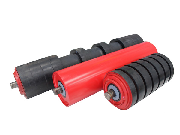
Surface-friction friction idlers use a high-friction shell material—typically rubber with aggressive tread patterns, ceramic tile linings, or bonded abrasive coatings—to increase the coefficient of friction between the belt and the idler surface. This increased friction converts a portion of the belt's kinetic energy into heat at the contact interface, creating a continuous retarding force proportional to belt speed and contact load.
Internal Brake Mechanism
Internal-brake friction idlers incorporate a mechanical or hydraulic brake device within the roller assembly. As the idler rotates, the brake mechanism generates a controlled torque that resists rotation, creating a retarding force transmitted through the belt-idler contact. Internal brake designs allow adjustable friction levels and can be configured for activation only during overspeed conditions, leaving the idler free-rolling during normal operation.
Primary Applications of Friction Idlers in Conveyor Systems
Friction idlers are deployed in specific conveyor configurations where belt motion control beyond standard drive braking is required. The following applications represent the most technically significant use cases:
Application 1: Steep Declined Conveyors and Regenerative Systems
On declined conveyors where the material load drives the belt forward (regenerative operation), the belt can accelerate beyond design speed if the drive system fails or loses control. Friction idlers installed at regular intervals along the decline provide distributed speed damping that prevents belt runaway. This application is common in underground mine decline conveyors, open-pit ramp conveyors, and wharf-to-stockpile gravity-fed systems.
Application 2: Long Inclined Conveyors with Tension Stabilization
On long inclined conveyors (exceeding 500 m), belt tension variations due to material loading transients can cause belt sag, slip at drive pulleys, and uneven idler loading. Friction idlers installed on the return run create a controlled back-tension that stabilizes belt tension along the conveyor length, reducing the severity of tension fluctuations and improving overall system reliability.
Application 3: Emergency Stop Speed Reduction
During emergency stop events on high-inertia conveyor systems, the belt and material load continue moving after drive power is cut. Friction idlers with internal brake mechanisms activated by overspeed sensors provide supplementary stopping force distributed along the belt path, reducing stopping distance and preventing material spillage during emergency deceleration.
Application 4: Downhill Stockpile Feed Conveyors
Conveyors feeding downhill into stockpiles or bins frequently operate in regenerative mode, where the material load generates more energy than the belt's rolling resistance consumes. Friction idlers absorb this excess energy, allowing the drive system to operate at or near zero net power rather than acting as a continuous brake. This reduces drive motor heating and extends drive component life.
Application 5: Conveyor Systems with Variable Loading Conditions
Conveyors that alternate between loaded and empty conditions—or between heavy and light material loads—experience significant tension and speed variations. Friction idlers provide a consistent retarding force that dampens these variations, improving belt tracking stability and reducing the dynamic loading on pulleys and structures.
Design Types and Construction of Friction Idlers
Friction idlers are available in several design configurations tailored to specific application requirements:
Fixed-Friction Surface Idlers
The simplest friction idler design features a high-friction rubber or ceramic shell permanently bonded to the roller core. The friction coefficient is fixed at the manufacturing stage and cannot be adjusted in the field. Fixed-friction idlers are economical and maintenance-free but provide a constant retarding force regardless of belt speed or loading conditions.
Adjustable Internal Brake Idlers
Adjustable friction idlers incorporate an internal disc brake, drum brake, or magnetic particle brake that can be set to a specific torque level. The brake torque is transmitted through the roller shaft to the shell, creating a controllable retarding force. Adjustment is typically achieved through an external handwheel or set screw accessible from the idler end cap.
Overspeed-Activated Brake Idlers
Overspeed-activated friction idlers incorporate a centrifugal or electronic speed-sensing mechanism that engages the internal brake only when belt speed exceeds a preset threshold. During normal operation, the idler rotates freely with minimal resistance. This design is preferred for applications where continuous friction would cause excessive heat generation or unnecessary power consumption during normal-speed operation.
Hydraulic Retarder Idlers
For high-power applications, hydraulic retarder friction idlers use a fluid coupling mechanism to generate braking torque proportional to rotational speed. Hydraulic retarders provide smooth, progressive braking and excellent heat dissipation, making them suitable for continuous regenerative operation on steep declines with heavy material loads.
Selection Criteria for Friction Idler Specification
Specifying the correct friction idlers for a conveyor system requires careful analysis of operational parameters. Key selection criteria include:
Required retarding force per idler: Calculate from the net driving force generated by the material load on the decline, divided by the number of friction idlers in the system. Typical retarding force per idler ranges from 500 N to 5,000 N depending on belt width, material density, and incline angle.
Belt speed operating range: Friction idler performance varies with speed. Surface-friction designs provide retarding force proportional to speed; internal brake designs provide more consistent torque across the speed range.
Heat dissipation capacity: The friction energy converted to heat must be dissipated to prevent shell overheating. Verify that the idler's thermal dissipation rate exceeds the maximum continuous friction power under worst-case operating conditions.
Bearing load rating: Friction idler bearings must support both the vertical belt load and the axial loads generated by the braking mechanism. Specify bearings rated for the combined load at the maximum operating temperature.
Environmental conditions: Dust, moisture, and ambient temperature affect friction coefficient stability and brake mechanism reliability. Sealed brake housings and corrosion-resistant materials are essential for outdoor and underground installations.
Installation and Commissioning Best Practices
Proper installation and commissioning of friction idlers is critical for achieving the specified retarding performance. Key practices include:
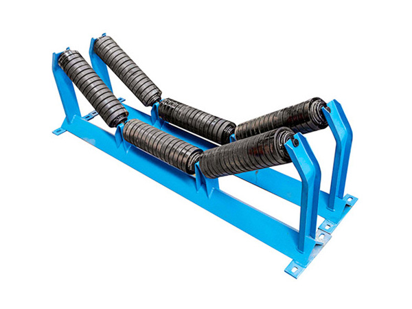
Position along the conveyor: Distribute friction idlers evenly along the declined or inclined section. Avoid concentrating friction idlers at a single location, which creates localized belt tension spikes and heat concentration.
Spacing: Typical friction idler spacing on declined conveyors is 10–30 m, depending on the number of friction idlers required and the belt's structural support requirements.
Brake torque setting: For adjustable friction idlers, set the initial brake torque to 50–70% of the calculated requirement and increase incrementally during commissioning while monitoring belt speed, tension, and idler shell temperature.
Temperature monitoring: Install shell temperature sensors on at least 20% of friction idlers during the commissioning period. Verify that shell temperature remains below the manufacturer's maximum rating (typically 80–100°C for rubber-shelled idlers) under sustained operation.
Integration with drive brake system: Coordinate friction idler settings with the drive station brake system to ensure smooth, progressive stopping during emergency events without belt tension overloads.
Maintenance Requirements for Friction Idlers
Friction idlers require more frequent and more detailed maintenance than standard free-rolling idlers due to the heat, wear, and mechanical complexity associated with their braking function. Recommended practices include:
Shell temperature monitoring: Check shell temperature at every scheduled inspection (every 1,000–2,000 operating hours). Abnormally high temperatures indicate excessive brake torque, inadequate heat dissipation, or bearing failure.
Friction surface wear measurement: For surface-friction idlers, measure the friction surface depth every 2,000–3,000 operating hours. Replace the idler when friction surface depth falls below 50% of original specification.
Brake mechanism calibration: For adjustable and overspeed-activated friction idlers, verify brake torque settings every 3,000–5,000 operating hours. Recalibrate if torque has drifted more than 10% from the specified value.
Bearing inspection: Bearings in friction idlers operate at higher temperatures and loads than standard idler bearings. Inspect every 1,500–2,000 operating hours; replace when radial play exceeds 0.4 mm or when bearing noise is detectable.
FAQ: Friction Idlers Applications in Conveyor Belt Systems
Q1: Can friction idlers replace a drive station brake system?
No. Friction idlers provide supplementary braking and speed control but are not designed to replace the primary brake system at the drive station. Drive station brakes provide the high-torque, rapid-response stopping capability required for emergency stops. Friction idlers provide distributed, progressive speed damping that reduces the load on the primary brake system and prevents belt runaway between the drive and tail pulleys.
Q2: Do friction idlers increase conveyor power consumption?
Yes, friction idlers increase power consumption on inclined conveyors where the drive must overcome the additional friction resistance. On declined regenerative conveyors, friction idlers actually reduce the net regenerative power that the drive system must absorb, which can reduce drive motor heating and extend drive component life. The net energy impact depends on the specific conveyor configuration and operating conditions.
Q3: What is the maximum incline angle where friction idlers are effective?
Friction idlers are effective on declined conveyors with angles from 5° to 25°. Above 25°, the material load driving force typically exceeds the practical retarding capacity of distributed friction idlers, and specialized high-angle conveyor designs (pipe conveyors, pocket belts) with dedicated braking systems are required.
Q4: How many friction idlers does a typical declined conveyor require?
The number of friction idlers required depends on the conveyor's geometry, material load, and required speed control. A typical specification places friction idlers at every 3rd to 5th idler station along the declined section, with standard free-rolling idlers at intermediate positions. Detailed engineering analysis using the DIN 22101 or CEMA calculation methodology is required for each installation.
Q5: Are friction idlers suitable for reversible conveyors?
Surface-friction friction idlers are inherently bidirectional and suitable for reversible operation. Internal brake designs may require symmetrical brake configurations or disengagement during reverse travel. Specify reversibility requirements explicitly during procurement to ensure compatible friction idler selection.
Conclusion
Friction idlers provide an essential distributed braking and speed-control function in inclined and declined conveyor systems, complementing drive station brakes with progressive, continuous retarding force along the belt path. Their applications—ranging from steep decline runaway prevention and emergency stop assistance to tension stabilization and regenerative power management—make them indispensable safety and performance components in mining, cement, and bulk terminal conveyor operations.
For conveyor designers and procurement professionals, specifying friction idlers with appropriate retarding force capacity, heat dissipation capability, and integration with the primary brake system is a direct investment in conveyor safety and operational reliability. Proper selection, installation, and maintenance of friction idler systems deliver measurable returns in reduced belt runaway risk, improved stopping performance, and extended drive system component life.
References
DIN 22101:2011. Continuous Conveyors – Belt Conveyors for Loose Bulk Materials – Basis for Calculation and Dimensioning. Berlin: DIN Deutsches Institut für Normung e.V., 2011.
Conveyor Equipment Manufacturers Association (CEMA). Belt Conveyors for Bulk Materials. 7th ed. Naples, FL: CEMA, 2014.
Hager, M. "The Design of Belt Conveyors for Declined Operation – Braking and Speed Control Strategies." Bulk Solids Handling, vol. 16, no. 1, 1996, pp. 61–72.
Kessler, F. "Friction Idler Systems for Regenerative Conveyor Operation." Proc. of Beltcon 14, Johannesburg, 2007.
Lodewijks, G. "Dynamics of Belt Systems: Braking and Speed Control Strategies for Declined Conveyors." Particle & Particle Systems Characterization, vol. 22, no. 5, 2005, pp. 328–340.

Contact Us
Tel:8615031765579
WhatsApp:+8615031765579
E-mail:905675277@qq.com
Add:Likou Village, Chenzhuang Town, Xian County, Hebei Province, China
Url:https://www.yxidlerrollers.com