







- Site Navigation -
Three Section Idlers Design for Heavy Duty Conveyors: Engineering Guide
Author:yuexing Date:2026-07-18 09:56:31 Hits:170
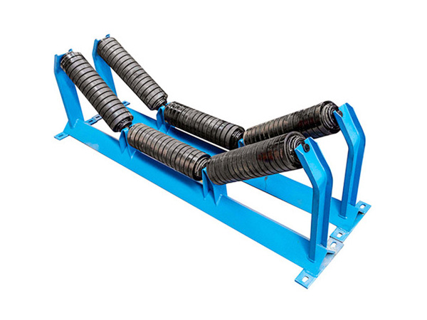
Heavy duty conveyor systems—those handling materials at rates above 3,000 tonnes per hour, with belt widths exceeding 1,200 mm and operating in mining, port, and mineral processing environments—demand idler assemblies engineered for sustained performance under extreme loading conditions. Three section idlers, comprising a horizontal center roll and two angled side rolls, are the standard troughing configuration for carrying idlers in these demanding applications. However, the difference between a three section idlers assembly that survives 50,000 operating hours and one that fails at 10,000 hours lies in design details that many procurement specifications overlook. This engineering guide examines the critical design parameters, material choices, and manufacturing standards that distinguish high-performance three section idlers for heavy duty conveyors from standard catalog offerings.
Core Design Principles of Three Section Idlers
The three section idlers configuration is defined by three geometric parameters that directly influence material containment, belt support, and load distribution:
Trough Angle Selection and Its Impact on Performance
The trough angle—the inclination of the side rolls relative to the horizontal center roll—determines the material cross-sectional area on the belt and the force distribution across the three rolls. Standard trough angles include 20°, 30°, and 45°, each suited to specific material characteristics:
20° trough angle: Used for fine, free-flowing materials (grain, sand) where a wide, shallow trough maximizes cross-sectional area without material surcharge angle concerns
30° trough angle: The most common configuration for general bulk handling (coal, limestone, aggregate), providing a balance between material containment and belt flex fatigue
45° trough angle: Applied for materials with steep surcharge angles or where maximum containment is required (iron ore, copper concentrate), but imposes higher flex fatigue on the belt at the transition from flat to troughed profile
In heavy duty applications, the trough angle selection must also account for the belt transition distance at the head and tail pulleys. CEMA recommends a minimum transition distance of 5.3 times the belt width for 45° trough angles on steel-cord belts (e.g., 8.0 m for a 1,500 mm belt), compared to 3.3 times belt width for 30° troughs (5.0 m for the same belt). Inadequate transition distance causes excessive edge tension and premature belt failure at the transition idlers.
Load Distribution Across the Three Rolls
In a three section idlers assembly, the material load is distributed unevenly across the three rolls. For a 30° trough angle carrying a typical bulk material, the approximate load distribution is 55–60% on the center roll and 20–22% on each side roll. This asymmetric distribution means the center roll bearings experience significantly higher loads than the side rolls, and must be specified accordingly. In heavy duty applications, a common design error is specifying identical bearings for all three rolls—the center roll should use a larger or higher-capacity bearing (e.g., 6310 series for center, 6208 series for sides) to match the actual load distribution.
For 45° trough angles, the center roll load share increases to approximately 65–70%, making the bearing specification differential even more critical. Some manufacturers offer asymmetric three section idlers designs with larger-diameter center rolls to distribute the load more effectively across the bearing contact area.
Roller Tube Design for Heavy Duty Service
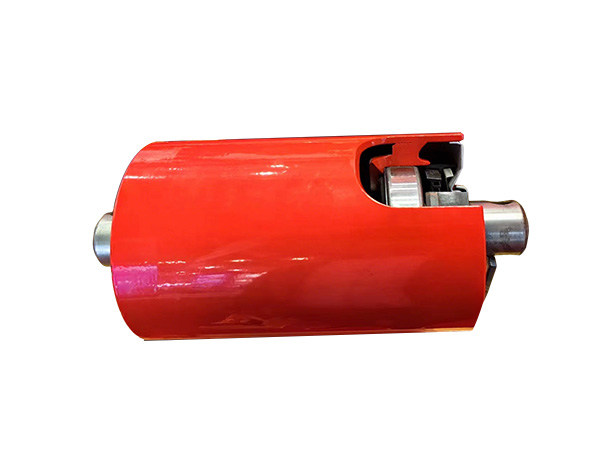
The roller tube is the primary structural element of each roll section in three section idlers assemblies. In heavy duty applications, tube design must address both static load capacity and dynamic wear resistance:
Wall Thickness and Diameter Selection
For heavy duty conveyors handling materials with bulk densities above 1.8 t/m³ and belt widths above 1,200 mm, minimum roller specifications include:
Tube diameter: 133 mm (5.25") minimum for 1,200 mm belts; 152 mm (6") for 1,400–1,800 mm belts; 194 mm (7.6") for 2,000 mm+ belts
Wall thickness: 5.0 mm minimum for non-abrasive applications; 6.0–8.0 mm for abrasive materials (iron ore, copper, bauxite); up to 10 mm for extreme impact zones
Tube material: ERW steel pipe Grade 250 minimum; Grade 350 for highly abrasive applications; seamless pipe for extreme loading conditions
Increasing wall thickness from 4.5 mm to 6.0 mm on a 152 mm diameter roller approximately doubles the tube bending resistance and increases fatigue life by 40–60%. For a conveyor handling 5,000 t/h of iron ore, this 1.5 mm wall thickness increment extends roller service life from approximately 12,000 hours to 18,000–20,000 hours, with a cost premium of less than 15% per unit.
Bearing and Seal System Design
Bearing selection is the most critical reliability parameter for three section idlers in heavy duty service. The bearing must accommodate high radial loads, moderate axial loads from belt tracking forces, and operate reliably in contaminated environments with minimal maintenance access. Key design decisions include:
Bearing Type and Size
Deep-groove ball bearings (single-row, double-shielded) are the industry standard for three section idlers. For heavy duty carrying idlers, specify:
Center roll: 6308-6310 series (40–50 mm bore) for 1,200–1,600 mm belts; 6312-6314 series for 1,800 mm+ belts
Side rolls: 6208-6210 series (40–50 mm bore) at 30° trough; 6308 series at 45° trough where side roll loading is proportionally higher
Bearing rating: Minimum C/P ratio (dynamic capacity / equivalent load) of 4.0 for continuous operation; 6.0+ for extended service life targets above 40,000 hours
Sealing System Architecture
The seal system is the primary defense against contamination-induced bearing failure, which accounts for over 50% of idler replacements in heavy duty applications. Modern three section idlers employ multi-stage sealing architectures that combine multiple barrier elements:
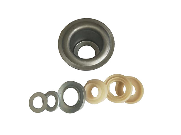
Inner seal: Nitrile rubber lip seal (contact type) providing primary dust and moisture exclusion at the bearing inner ring
Outer labyrinth: Machined metal labyrinth gap with multi-step radial and axial passages, creating centrifugal dust rejection at operating speeds above 300 RPM
Grease barrier: A packed grease cavity between the inner lip seal and outer labyrinth, providing both lubrication and a secondary contamination barrier
V-ring external seal: An elastomeric V-ring on the shaft exterior, preventing dust ingress at the shaft-to-housing interface
This four-stage sealing system has proven effective in maintaining bearing integrity for 40,000+ operating hours in mining environments with dust concentrations exceeding 100 mg/m³. In comparative field tests, idlers with four-stage sealing achieved 3.5 times the bearing life of units with standard double-lip contact seals under identical operating conditions.
Frame and Bracket Design for Structural Integrity
The three section idlers frame must maintain precise roll alignment under sustained high loading while resisting fatigue from cyclic belt passage and material impact. Frame design considerations for heavy duty applications include:
Material: Hot-rolled channel section (minimum 100 mm × 50 mm × 5 mm) or fabricated plate bracket with minimum 8 mm plate thickness
Corrosion protection: Hot-dip galvanized (minimum 65 μm zinc coating) for outdoor and corrosive environments; painted systems for indoor dry applications
Roll position accuracy: Side roll angle tolerance ±1°; center-to-side roll spacing tolerance ±2 mm; all three rolls must be coplanar within 1.5 mm to prevent asymmetric belt loading
Shaft retention: Positive locking mechanisms (split pins, circlips, or bolted caps) to prevent shaft migration under cyclic loading—shaft walk-out is a common failure mode in poorly designed heavy duty idlers
Frequently Asked Questions
Why choose three section idlers over two-section or five-section configurations?
Three section idlers are the optimal balance between material containment, belt flex fatigue, and structural simplicity for most heavy duty applications. Two-section idlers (flat center + two side rolls at steep angles) create a sharp bending point at the center-to-side junction, accelerating belt fatigue. Five-section idlers (additional intermediate rolls) provide smoother belt transitions but add complexity, cost, and weight without proportional performance improvement for most applications above 1,200 mm belt width.
What is the recommended bearing C/P ratio for three section idlers in mining applications?
For continuous operation in mining environments with high contamination levels, specify a minimum C/P ratio of 4.0 for standard carrying idlers and 6.0+ for impact zone idlers. Higher C/P ratios directly extend bearing L10 life—the theoretical fatigue life rating increases proportionally with the cube of the C/P ratio, making bearing overspecification one of the most cost-effective reliability investments in heavy duty idler design.
How do I verify that three section idlers are correctly aligned on my conveyor?
Use a laser alignment system to verify that all three rolls at each idler station are coplanar within 1.5 mm and that the trough angle matches the design specification within ±1°. Misaligned idlers create lateral belt forces that accelerate edge wear and increase tracking problems. Conduct alignment verification during initial installation and at annual maintenance intervals.
Can three section idlers be used on reversible conveyors?
Yes, standard three section idlers are bidirectional by design—the trough geometry functions identically regardless of belt travel direction. However, on reversible conveyors, ensure that the belt transition zones at both head and tail pulleys provide adequate transition distance for the selected trough angle, since both pulleys now function as discharge points requiring flat-to-trough transitions.
Conclusion
Designing three section idlers for heavy duty conveyors requires attention to details that extend far beyond selecting a catalog idler rating. The trough angle, load distribution across the three rolls, roller tube wall thickness, bearing size and C/P ratio, multi-stage sealing architecture, and frame structural integrity all interact to determine whether an idler assembly delivers 10,000 or 50,000+ hours of reliable service. By applying the engineering principles outlined in this guide—differentiated bearing specifications matching actual load distribution, four-stage sealing systems for contaminated environments, and robust frame design with positive shaft retention—procurement teams can specify three section idlers that meet the demanding reliability requirements of modern heavy duty conveyor operations.
References
Conveyor Equipment Manufacturers Association (CEMA). CEMA 7th Edition — Belt Conveyors for Bulk Materials. CEMA, 2014.
Molnár, V., Fedorko, G., Stehlíková, B., et al. "A Failure Analysis of Idler Rolls of Belt Conveyors." Engineering Failure Analysis, vol. 45, 2014, pp. 155-165.
Harrison, A. "Determining the Life of Conveyor Rollers Using Fatigue Theory." Bulk Solids Handling, vol. 25, no. 5, 2005, pp. 290-295.
Fedorko, G., and Molnár, V. "Determination of the Idler Rollers Bearing Load." Research in Engineering, vol. 22, 2013, pp. 45-52.
Zhang, Y., Yang, X., and Meng, L. "Review of Belt Conveyor Idler Roller Research." Mining Science and Technology, vol. 33, no. 3, 2023, pp. 415-428.

Contact Us
Tel:8615031765579
WhatsApp:+8615031765579
E-mail:905675277@qq.com
Add:Likou Village, Chenzhuang Town, Xian County, Hebei Province, China
Url:https://www.yxidlerrollers.com