







- Site Navigation -
Conveyor Idler Shaft Design and Strength Analysis Without the Textbook Theory
Author:yuexing Date:2026-08-21 08:16:04 Hits:93
Every idler we have pulled apart in the field tells the same story before anything else: the shaft either bent, cracked at the fillet, or walked out of its bearing seat. It is almost never the tube that fails first, and it is almost never a mystery why — the shaft was undersized for the duty or the wrong material was specified from the start. This article walks through what actually matters in conveyor idler shaft design, written for the engineer or buyer who needs to specify correctly without wading through derivation. We start with the actual load path and work outward to material choice, diameter sizing, and the details that separate a shaft that lasts from one that bends within a season.
How the Load Actually Gets to the Shaft
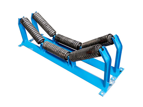
The belt load, material weight, and the roller itself all press down through the bearing onto the shaft. That is a radial load, but it is not uniform — the centre roll in a three-roll trough carries 55–70% of the total load, so its shaft section works harder than the side roll shafts. On impact idlers, the dynamic load spike at the bearing seat can run 1.5–2 times the steady-state load, which matters enormously for shaft stress but is routinely ignored in simple static calculations.
The shaft sees bending moment from the load, torsion from belt drag and friction, and stress concentration at every shoulder, keyway and bearing seat step. A shaft that looks adequately sized by a simple bending stress check can still fail at the fillet radius where the section changes, because nobody ran the stress concentration factor. That step is where most of our field failures originate, and it costs nothing to check if you know the formula.
Sizing the Shaft Diameter
The quick sizing check most factories use is the bending stress formula: sigma equals M times c divided by I. Take the maximum bending moment from the load distribution, find the section modulus of the shaft at the most stressed point — usually at the bearing seat or mid-span — and confirm the resulting stress is below the allowable for the material. For AISI 1045 normalised steel, a common choice for conveyor idler shaft work, we keep bending stress below 90 MPa for continuous duty to leave room for dynamic peaks. That gives a minimum diameter, which then gets checked for deflection.
Deflection limits are often the real constraint. A shaft that is adequately strong can still sag under load enough to misalign the roller and cause belt tracking issues. The practical limit we use in our factory is L over 400 for simply supported shafts — a 400 mm span between bearing seats should not deflect more than 1 mm at mid-span. For shafts carrying impact idlers on heavy lines, we tighten that to L over 600. If the diameter calculation from stress passes but deflection fails, the diameter goes up until it does not.
Material Choices and When to Step Up
AISI 1045 normalised covers the majority of idler shaft applications. It machines cleanly, is readily available from most steel service centres, and delivers adequate strength at reasonable cost. AISI 4140 heat-treated is the right step up when the application pushes the limits — higher belt tensions, wider belts with heavier loads, or higher speeds that increase torsional stress from belt drag. The 4140 gives roughly 30–40% more yield strength than 1045, which can be the difference between a shaft that passes the check and one that requires a significantly larger diameter to do so.
For wash-down or wet applications, a galvanised or stainless shaft removes the corrosion risk that eventually attacks even painted carbon steel in constantly damp environments. The cost premium is real but the alternative — a corroded shaft that galling-seizes in the bearing seat — is worse, because it means cutting the bearing housing off the frame to remove the shaft.
The Details That Kill Shafts in Practice
Shaft failure almost never starts in the middle of a straight section. It starts at a geometric discontinuity: a sharp fillet at a bearing seat step, a keyway that was cut with a saw and not stress-relieved, a press-fit shoulder that introduced residual tensile stress. A well-designed conveyor idler shaft uses generous fillet radii at every section change — minimum 3 mm for shaft diameters up to 50 mm, scaling up with size. Keyways should be cut and then the surrounding area stress-relieved by heating to 550–600°C and cooling slowly, rather than left as-cut with stress risers. These are shop-discipline items, not design ones, and they are what separates a manufacturer who gets this right from one whose shafts fail at 15,000 hours.
Bearing seat fit is another detail that trips up factories new to idler production. The shaft should be ground to h6 tolerance at the bearing seat — close enough to ensure the inner race does not spin on the shaft, loose enough to allow press-fitting without generating hoop stress. A shaft that spins inside its bearing is a catastrophic failure that destroys the bearing and damages the housing in minutes.
Fatigue Is the Real Threat
A shaft under cyclic bending load fails from fatigue, not from a single overload event. The S-N curve for a notched carbon steel shaft in rotating bending shows that at a stress amplitude of about 200 MPa, the fatigue limit is reached in roughly 100,000 cycles — which on a conveyor idler at normal operating speeds translates to a few months of continuous running. For conveyor idler shaft design, the allowable alternating stress should be set below the fatigue limit with a safety factor of at least 2 on endurance. That is why we keep bending stress below 90 MPa for 1045 — it sits comfortably below the endurance limit and gives margin for stress concentrations we have not calculated.
FAQ
What diameter does a conveyor idler shaft need for a 1,200 mm belt?
There is no single answer — it depends on the load per idler station, the span between bearing seats, and the idler spacing. As a rough reference, our factory typically fits 40–45 mm diameter shafts for standard 1,200 mm carrying idlers, stepping up to 50–60 mm for heavy-duty or impact zones. That needs to be verified by actual calculation for the specific duty, not relied on as a rule of thumb.
Can the centre and side roll shafts be different sizes?
Yes, and they should be if the load distribution is properly accounted for. The centre roll carries 55–70% of the load, so it often needs a larger diameter or a higher-strength material than the side rolls. Matching the shaft to the actual load split is one of the cheapest ways to avoid premature failures on the centre position.
Why do shafts crack at the bearing seat?
Because the section change creates a stress concentration. A sharp fillet radius at the step multiplies the local stress well above the nominal bending stress calculated for the shaft. Using generous fillet radii and avoiding sharp keyway ends controls this. The issue is almost always a manufacturing detail rather than a design error.
Is 1045 steel adequate for all idler applications?
For the majority of standard duty, yes. For high-tension wide belts, impact idlers, or high-speed conveyors, step up to 4140 heat-treated. For wet or corrosive environments, galvanised or stainless is worth the extra cost to avoid shaft seizure in the bearing seat.
Conclusion
A reliable conveyor idler shaft starts with a correct bending stress check, but that alone is not enough — deflection must be verified, fatigue limits respected, fillet radii made generous, and the material matched to the environment. The details that kill shafts in service — sharp fillet radii, undersized keyways, poor bearing seat fit — are shop-discipline problems as much as design ones, which means the choice of manufacturer matters as much as the specification itself. A buyer who understands what to ask for — fillet radii, stress relief, tolerance at the bearing seat — will get better shafts than one who simply asks for the price.
References
Shigley's Mechanical Engineering Design. Standard Handbook of Mechanical Engineering. McGraw-Hill, 10th edition, 2015.
Conveyor Equipment Manufacturers Association. CEMA 7th Edition — Belt Conveyors for Bulk Materials. CEMA, 2014.
Molnár, V., Fedorko, G., Stehlíková, B., et al. "A Failure Analysis of Idler Rolls of Belt Conveyors." Engineering Failure Analysis, vol. 45, 2014, pp. 155-165.
Harrison, A. "Determining the Life of Conveyor Rollers Using Fatigue Theory." Bulk Solids Handling, vol. 25, no. 5, 2005, pp. 290-295.

Contact Us
Tel:8615031765579
WhatsApp:+8615031765579
E-mail:905675277@qq.com
Add:Likou Village, Chenzhuang Town, Xian County, Hebei Province, China
Url:https://www.yxidlerrollers.com