







- Site Navigation -
Conveyor Idler Installation Guide: Step-by-Step for Plant Engineers
Author:yuexing Date:2026-09-08 19:37:52 Hits:195
The best time to catch an installation error is before the belt runs. A poorly installed idler will run badly — it will vibrate, cause belt mistracking, overload its bearing faster than it should, and usually fail within weeks or months rather than the years it was specified for. The cost of fixing it after the conveyor is running is at least three times the cost of installing it correctly in the first place, because the conveyor must be stopped, the belt threaded off or lifted, the idler accessed, and the whole process reversed. This guide covers the conveyor idler installation steps that matter, in the order that makes them easiest to do correctly, for crews working on shutdowns where time pressure is real and shortcuts are tempting.
Before You Start: Preparation and Component Checks
The first step in a good conveyor idler installation happens before anyone touches a tool. Verify that the correct idlers are on site — the correct diameter, length, load rating, and type for the position. Mismatched idlers are surprisingly common when multiple conveyor sections are being worked on simultaneously, and finding out after the conveyor is reassembled that a carrying idler was fitted where a return idler should have been is an expensive mistake to correct. Check the component condition of each idler: spin the roller by hand and verify it rotates freely and quietly with no grinding, clicking or rasping. A bearing that feels rough when spun by hand will feel much worse under load after installation. Check the sealing arrangement — the lip seals and any external V-rings should be intact and not displaced from their grooves.
Verify that the mounting hardware is present and correct: the correct grade and length of mounting bolts, lock washers or nuts with prevailing torque, and any shims or spacers specified for the installation. Check the conveyor string for structural integrity before mounting new idlers — a sagging or distorted string will defeat good idler alignment immediately, and it is easier to address the structural problem now than after the idlers are in place.
Step 1: Remove the Old Idler and Inspect the Mounting Zone
Before removing the old idler, mark the mounting positions on the string using a centre punch or paint marker — this makes it easier to set the new idler in the same location and to check whether the existing mounting holes have elongated from repeated removal cycles. Elongated mounting holes are a sign of incorrect bolt grade or torque, or a string that is moving more than it should, and they need to be addressed before the new idler is fitted.
Remove the old idler and clean the mounting faces. Remove all debris, old shims, and any packing material from the mounting area. Inspect the string face for corrosion, distortion, or damage at the mounting points. If the mounting faces are corroded to the point where a flat mounting surface cannot be established by cleaning, address this before proceeding — a new idler mounted on a corroded, uneven surface will be misaligned from the start.
Step 2: Position and Orient the New Idler Correctly
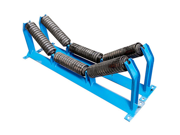
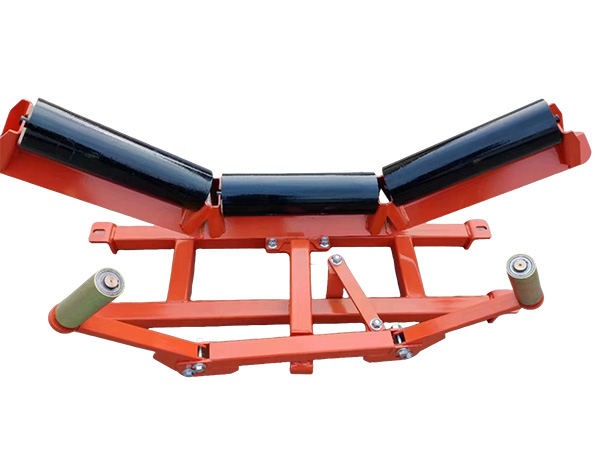
Position the new idler before tightening any bolts. On a trough set, the centre roll must be centred on the belt axis and set to the correct trough angle — 20, 35 or 45 degrees depending on the specification. The side rolls must be symmetrically positioned relative to the centre roll and set to the same trough angle as each other. Use a digital angle finder or bevel protractor against the roller face to set the trough angle precisely before any bolt is tightened. This is the step most commonly skipped under time pressure, and it is the step that most directly determines whether the belt tracks correctly after installation.
On reversible conveyors, the trough angle symmetry is even more critical because any asymmetry produces belt tracking drift in both directions. On single-direction conveyors, a slightly asymmetric trough set will typically produce tracking drift toward the lower side roll — which is useful diagnostic information if it happens, but much better avoided entirely by setting the angles correctly at installation.
Step 3: Apply the Correct Bolt Torque
Torque settings for conveyor idler installation are determined by the bolt grade and the thread size. For M16 Grade 8.8 bolts — the most common size in idler mounting — the recommended torque is 180–200 Nm for lightly oiled threads. For M20 Grade 8.8 bolts, 350–380 Nm. For M16 Grade 10.9 bolts, 260–290 Nm. These figures assume lightly oiled threads; dry threads require approximately 25% higher torque to achieve the same clamp load due to increased friction. Use a calibrated torque wrench — not feel, not experience — for the final torque application. Impact wrenches are useful for removing old bolts but are too inconsistent for final installation torque on Grade 8.8 or 10.9 hardware.
Apply torque in stages: first snug all bolts evenly to seat the idler on the mounting face, then apply final torque in a cross-pattern to ensure even clamp load. Uneven torque on a four-bolt pattern will tilt the idler and create the misalignment that the previous step was meant to prevent.
Step 4: Verify Free Rotation After Mounting
After torquing the mounting bolts, spin every roller on the installed idler by hand and verify it rotates freely. Any resistance, grinding, or catching is an immediate problem — the shaft may be bearing against the housing, the idler may have been tilted by uneven bolt torque, or the bearing may have been damaged during handling. A roller that is hard to spin by hand will be harder still under load, and the additional bearing load from belt tension and material weight will accelerate the bearing toward failure. This check takes five seconds and catches problems that would otherwise manifest as premature bearing failures within weeks of conveyor idler installation.
Step 5: Pre-Commissioning Belt Run and Tracking Check
Before introducing material to the conveyor, run the empty belt for a full circuit and observe the tracking behaviour at the newly installed idler. The belt should run centred on the idler without consistently tracking toward one side. Any consistent tracking drift at this stage is easier to correct before material is loaded — either by adjusting the trough angle of the adjacent idlers or by checking the symmetry of the newly installed set. If tracking correction requires more than 2 degrees of trough angle adjustment on adjacent idlers, the newly installed idler should be rechecked for correct positioning before making broader adjustments.
Run the belt empty for at least 30 minutes and observe: any idler that develops vibration, noise, or visible movement of the frame should be rechecked. After the empty run, stop the belt and re-torque the mounting bolts — thermal cycling and initial loading can settle the hardware, and a loose bolt that was identified at 180 Nm may have dropped to 140 Nm after the first thermal cycle.
Step 6: Document the Installation
Record what was installed, where, when, and by whom. The installation record should note the idler type and serial number or batch reference, the mounting position (conveyor section and station number), the date, the technician name, and any observations during installation — particularly any deviations from the standard procedure, any structural issues identified, or any idlers that were replaced more than once during the same shutdown. This record is the data that makes future maintenance planning possible. A plant that cannot answer the question "when were the idlers at positions 45 through 60 on conveyor C-7 last replaced" is running its maintenance programme on memory rather than data, and memory is unreliable at 3 AM during a breakdown.
FAQ
What torque should be used for conveyor idler installation bolts?
For M16 Grade 8.8 bolts, 180–200 Nm with lightly oiled threads. For M20 Grade 8.8, 350–380 Nm. For Grade 10.9 hardware at the same sizes, increase to 260–290 Nm and 520–560 Nm respectively. Always verify the bolt grade on the hardware before applying torque — mixed grades on site are common and applying the wrong torque to a Grade 10.9 bolt (using Grade 8.8 values) risks overloading and stretching the bolt.
How do I set the trough angle correctly during idler installation?
Use a digital angle finder or bevel protractor against the roller face, not the frame. Set the centre roll first to the design trough angle (typically 20, 35 or 45 degrees), then set each side roll to the same angle using the centre roll as the reference. The side rolls should be symmetric — equal angle on both sides. Check symmetry by measuring the distance from each side roll to the centre roll at the belt line; they should be equal.
Should I replace all idlers on a conveyor section during a shutdown?
It depends on the age distribution and condition of the existing idlers. If the idlers being replaced are at or near their expected lifespan, replacing the adjacent idlers at the same time avoids a repeat shutdown in 6–12 months. If the adjacent idlers are relatively new, replacing them is not justified. The installation record from previous work is what makes this decision easy — without it, the default tends toward replacing too much, which wastes budget, or too little, which wastes future shutdown time.
What is the most common conveyor idler installation mistake?
Skipping the trough angle verification before final torque. It takes two minutes with an angle finder and it is the step most likely to be omitted when crews are under time pressure. The result is a subtly misaligned idler that causes belt mistracking, accelerated bearing loading on adjacent idlers, and premature failures that are misdiagnosed as quality problems rather than installation problems.
Conclusion
Good conveyor idler installation is mostly about discipline: preparing before starting, verifying the correct components, setting trough angles before tightening, applying correct torque with a calibrated tool, checking free rotation after mounting, and running the belt empty before introducing material. These steps are not time-consuming individually, and they collectively eliminate the installation errors that account for a significant fraction of early idler failures. A crew that follows this sequence consistently will have fewer unplanned stoppages, shorter shutdowns, and more predictable maintenance schedules — and that is ultimately what installation quality delivers.
References
Conveyor Equipment Manufacturers Association. CEMA 7th Edition — Belt Conveyors for Bulk Materials. CEMA, 2014.
Molnár, V., Fedorko, G., Stehlíková, B., et al. "A Failure Analysis of Idler Rolls of Belt Conveyors." Engineering Failure Analysis, vol. 45, 2014, pp. 155-165.
Harrison, A. "Determining the Life of Conveyor Rollers Using Fatigue Theory." Bulk Solids Handling, vol. 25, no. 5, 2005, pp. 290-295.
Fedorko, G., and Molnár, V. "Determination of the Idler Rollers Bearing Load." Research in Engineering, vol. 22, 2013, pp. 45-52.

Contact Us
Tel:8615031765579
WhatsApp:+8615031765579
E-mail:905675277@qq.com
Add:Likou Village, Chenzhuang Town, Xian County, Hebei Province, China
Url:https://www.yxidlerrollers.com