







- Site Navigation -
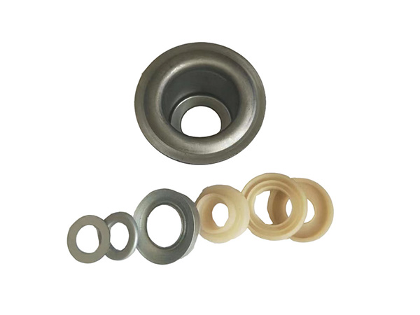
Complete Guide to Selecting Load Bearing Idler Assemblies for Industrial Conveyors
Author:yuexing Date:2026-07-08 20:19:57 Hits:138
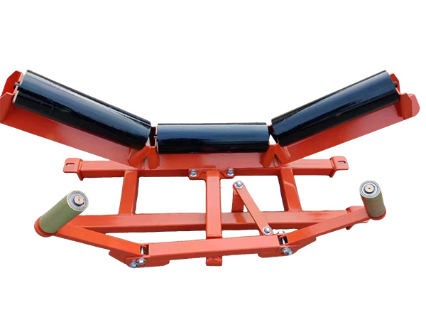
Selecting the correct load bearing idler assemblies is one of the most critical decisions in conveyor system design. An improperly sized or misaligned idler can lead to premature belt wear, excessive power consumption, structural fatigue, and unplanned downtime that costs mining and bulk material handling operations thousands of dollars per hour. This comprehensive load bearing idler assemblies selection guide draws on over two decades of field experience across mining, cement, and port handling applications to help procurement engineers and plant managers make informed decisions.
Understanding Load Bearing Idler Assemblies: Core Components and Function
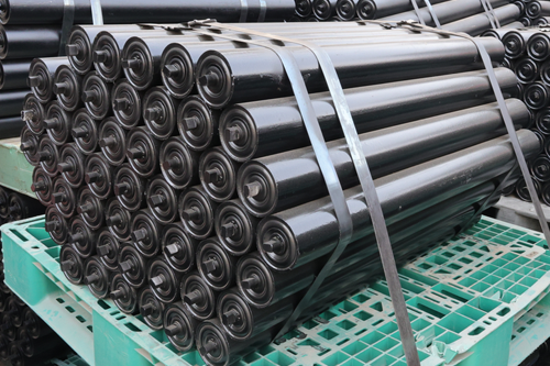
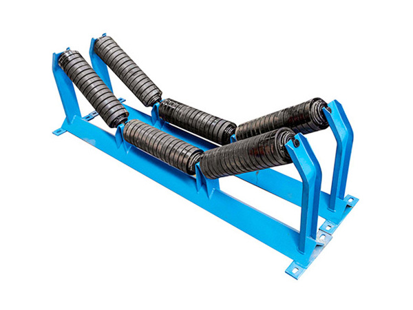
Load bearing idler assemblies consist of three principal elements: the roller tube, the bearing housing, and the support bracket (or frame). Together, these components support the conveyor belt and its material load, maintaining proper belt alignment while minimizing rotational resistance. In a typical bulk handling installation carrying 2,000–5,000 tonnes per hour, a single idler station may bear static loads exceeding 5 kN and dynamic loads (including impact) of 10–15 kN during operation.
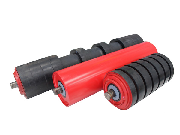
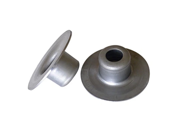
The roller tube is typically manufactured from steel pipe (Grade 250 or higher) with wall thicknesses ranging from 4 mm to 8 mm depending on the application. For highly corrosive environments such as fertilizer handling or coastal port operations, polyurethane-lined or stainless steel rollers provide extended service life. The bearing housing encloses a sealed anti-friction bearing—most commonly a deep-groove ball bearing (6200 or 6300 series) with a multi-lip contact seal to prevent dust and moisture ingress.
Key Selection Criteria for Load Bearing Idler Assemblies
When evaluating load bearing idler assemblies for a specific application, engineers should consider the following factors in order of priority:
1. Load Rating and Belt Width Compatibility
The fundamental selection parameter is the load rating, expressed in kilonewtons (kN) per idler station. CEMA (Conveyor Equipment Manufacturers Association) standards classify idlers into five series (A through E), with load capacities ranging from approximately 250 N to over 11,000 N per roll. For a standard 1,000 mm belt carrying 3,000 t/h of coal over a 1,200 m run, a three-roll carrying idler rated at 5.4 kN (CEMA C) is typically specified for troughing sections, while impact idlers at feed points require ratings of 10.8 kN or higher.
Matching the idler series to the belt width is equally important. Standard configurations include:
500–650 mm belts: 108 mm (4.25") roller diameter, CEMA B series
800–1,000 mm belts: 127 mm (5") roller diameter, CEMA C series
1,200–1,800 mm belts: 152 mm (6") roller diameter, CEMA C or D series
2,000 mm+ belts: 152–194 mm (6–7.6") roller diameter, CEMA D or E series
2. Operating Speed and Bearing Selection
The rotational speed of the idler roller directly affects bearing life and seal integrity. At belt speeds above 4 m/s, the bearing RPM can exceed 1,000, generating significant heat and accelerating grease degradation. For high-speed applications (above 5 m/s), specify idlers with high-performance labyrinth seals and lithium-complex grease rated to 120°C. In our field experience, switching from standard contact seals to multi-lip labyrinth seals on high-speed installations has extended idler service life by 40–60%.
3. Environmental and Material Compatibility
The operating environment dictates material and coating choices for load bearing idler assemblies:
Standard dry bulk (coal, aggregate): Carbon steel with hot-dip galvanized frame, standard oil seals
Abrasive materials (iron ore, sand): Wear-resistant ceramic or polyurethane lagging on rollers, heavier wall thickness
Corrosive environments (fertilizer, salt, chemicals): 304/316 stainless steel or polymer-coated housings
High-moisture applications (wash plants, port stockpiles): Grease-packed bearings with triple-lip seals, galvanized or painted frames
4. Spacing and Installation Considerations
Idler spacing directly affects both the structural load on each assembly and belt sag between support points. For carrying idlers on troughing sections, standard spacing ranges from 1.0 m to 3.0 m depending on belt width and material bulk density. A useful rule of thumb: the maximum recommended idler spacing (in metres) is approximately belt width (in mm) divided by 500 for standard applications. For a 1,200 mm belt, this yields 2.4 m spacing—though this should be verified against the specific belt tension and load profile using CEMA calculation methods.
Return idlers typically require wider spacing (2.0–4.0 m) since they carry only the empty belt weight. Impact idlers at loading points should be spaced at 0.3–0.5 m intervals to absorb material impact energy and prevent belt damage.
5. Total Cost of Ownership vs. Initial Price
When comparing load bearing idler assemblies from different manufacturers, procurement teams should evaluate total cost of ownership (TCO) rather than unit price alone. A high-quality idler assembly priced 20–30% above the market average may deliver 50,000–80,000 operating hours, while a cheaper alternative may require replacement at 15,000–20,000 hours. Factoring in replacement labor, conveyor downtime, and production losses during changeovers, the lower-priced option often costs 2–3 times more over a 5-year lifecycle.
Common Selection Mistakes and How to Avoid Them
Through hundreds of conveyor audits across mining and industrial sites, we consistently observe the following selection errors:
Undersizing impact idlers: Using standard carrying idlers at feed points instead of properly rated impact assemblies, resulting in roller failure within 3–6 months
Ignoring belt speed in bearing selection: Specifying standard bearings for applications exceeding 4 m/s, leading to premature seal failure and bearing seizure
Neglecting environmental factors: Installing carbon steel idlers in corrosive environments without protective coatings, causing rust-jacking and structural failure within 1–2 years
Excessive idler spacing: Increasing spacing beyond CEMA recommendations to reduce initial cost, resulting in excessive belt sag, material spillage, and higher power consumption
Frequently Asked Questions
What is the standard service life of load bearing idler assemblies?
In properly selected and maintained installations, quality load bearing idler assemblies typically deliver 25,000–80,000 operating hours depending on the application severity. Mining and heavy-duty applications generally fall in the 25,000–40,000 hour range, while light-duty industrial applications may achieve 60,000+ hours.
How do I determine the correct load rating for my application?
Calculate the total load per idler station using material weight per metre, belt weight per metre, and idler spacing. Then apply a dynamic impact factor of 1.5–2.0 for feed points and 1.0–1.2 for standard carrying sections. Select an idler with a rated capacity at least 20% above the calculated load.
Can I use the same idler assemblies for both carrying and return runs?
While some installations use flat return idlers from the same manufacturer series, the loading conditions differ significantly. Return idlers support only the belt weight (typically 10–30 kg/m), while carrying idlers support both belt and material load (often 100–500 kg/m). Always verify that the return idler rating is adequate for the specific belt and tension conditions.
What maintenance is required for load bearing idler assemblies?
Modern load bearing idler assemblies with sealed-for-life bearings require minimal maintenance. However, a scheduled inspection program should include monthly visual checks for roller rotation, quarterly belt alignment surveys, and annual vibration analysis to detect bearing degradation before failure occurs.
Conclusion
Selecting the right load bearing idler assemblies requires a systematic evaluation of load requirements, belt speed, environmental conditions, and lifecycle costs. By following the criteria outlined in this guide and avoiding common selection pitfalls, plant engineers and procurement teams can ensure reliable conveyor performance, reduce unplanned downtime, and optimize total cost of ownership. When in doubt, consult with a qualified conveyor specialist who can perform site-specific calculations and recommend assemblies matched to your exact operating conditions.
References
Conveyor Equipment Manufacturers Association (CEMA). CEMA 7th Edition — Belt Conveyors for Bulk Materials. CEMA, 2014.
Lodewijks, G. "Two Decades of Dynamics of Belt Conveyor Systems." Bulk Solids Handling, vol. 22, no. 2, 2002, pp. 124-132.
Molnár, V., Fedorko, G., Stehlíková, B., et al. "A Failure Analysis of Idler Rolls of Belt Conveyors." Engineering Failure Analysis, vol. 45, 2014, pp. 155-165.
Harrison, A. "Determining the Life of Conveyor Rollers Using Fatigue Theory." Bulk Solids Handling, vol. 25, no. 5, 2005, pp. 290-295.
Zhang, Y., Yang, X., and Meng, L. "Review of Belt Conveyor Idler Roller Research." Mining Science and Technology, vol. 33, no. 3, 2023, pp. 415-428.

Contact Us
Tel:8615031765579
WhatsApp:+8615031765579
E-mail:905675277@qq.com
Add:Likou Village, Chenzhuang Town, Xian County, Hebei Province, China
Url:https://www.yxidlerrollers.com